After realizing that the use situation is more complicated than what they thought, the managers from the CMI project organized a second user workshop to check if the current floor plan fits the workflow of scanning patients in machines such as EGG, PET-MRI, MRI, and CT.
In the last workshop, a lot of time was spent discussing if the number of dressing rooms was enough for all the machines. In close collaboration with managers, my colleague Vedran Zerjav created an animated simulation using Flexsim that revealed the number of dressing rooms to be more than enough, according to the capacity predicted in the business case.

I found the simulation very nice to visualize the medical procedures, but not good enough to be used as a mediation tool during the workshop. Participants could not “touch” the simulation directly, and Vedran would not be able to change it so quickly as to follow the discussions. The simulation would become a bottleneck.
We decided to create another tool to support discussions. The design was already in late stage and the managers didn’t want to change the floor plan too much. This tool was supposed to give a focus to the discussion.
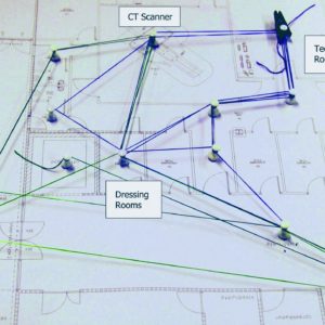
We developed a game for participants to trace the walking paths of medical procedures on top of the floor plan, using strings and paper pins. In the prototype below we try two different types of strings: wool and elastic fiber. We also played a bit with colors to indicate the role of the person walking (patients, nurses, or technicians). We called that “the knitting game”.

We could have used spaghetti diagrams, but as soon as the path is drawn on paper, it would be very hard to change. The strings are more flexible and diminishes the possibilities of one participant to dominate the discussion by holding the official pen. Stretching the strings actually required that participants collaborate to draw.

In the second workshop, participants were split in two groups according to the machines each hospital wanted to use. One group didn’t even try the game because they spotted so many problems in the floor plan that they found useless to draw the walking paths. The discussion in this group run in circles, with no means to make a design alternative.
When the other group was done, I suggested to bring the knitted board to the struggling group and let them design a combined vision for the floor plan. At one point, a participant pull out an unofficial sheet of paper and start sketching a new floor plan.

The architects followed closely the move. Instead of being skeptical about changes in the design, the managers embraced the alternative and asked the architects to quickly elaborate a polished version of the new layout still during the workshop. There were some further discussion and adjustment, but in the end, the participants agreed on fixing that layout.

I came back from the workshop thinking on a new tool that would allow the same level of flexibility provided by the strings to the floor plan itself. Drawing over the floor plan worked, but the dominance was clear.
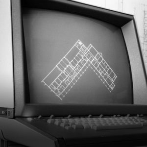
Together with my supervisor, I created a second prototype of the knitting game, now inside the computer, in the same environment that architects use to draw floor plans: Autodesk Revit. It is just a smart component that can be used to draw the walking paths, with the advantage of calculating automatically the walking distances and time. Stop times are represented by bubble sizes, a visualization pattern that I took from eye tracking studies.

The component is a modified version of the Path of Travel Distance that I found at RevCity and it is now available to download. I plan to write a tutorial on how to use it, but it works almost in the same way as in the the original family.
We tested the component in a classroom with Civil Engineering students. We asked them to redesign the floor plan while drawing the walking paths. The animation below shows snapshots saved every 5 minutes from one student.

I find quite interesting seeing layout and workflow evolving together. The metaphor of knitting keeps myself looking at both sides: the shape of space and the shape of flows. At least in the CMI project, it was not until the layout was designed that the flow started to take a clear shape. But as soon as that happened, the layout had to change, and then the flow, and then back to the layout, and so on.
It seems like there is a strong materiality in layouts and flows that can only be realized when they get a form. There are currently a lot of formats for designing layouts (like floor plans) and flows (flow diagrams, list of steps), but not many formats to knit them together. In participatory workshop, these two dimensions are typically discussed and constructed at the same time. Revit might not be the best mediation tool to use during a workshop, but we are going to test it.
Perhaps it would be more suitable doing a full-size mockup, something like the web of Tomás Saraceno that I saw in Helsinki.

Those strings allover the place made me think about all the invisible social relationships we have, especially those that depends on place. Turning such relationships visible is one way I found to make a case for participation in construction projects. If you don’t have the users participating, you cannot specify the walking paths accurately. I hope that I’ll find a way to visualize aspects of healthcare activities other than just walking paths.